Product Description
Welded Metric Roller Drive Conveyor Chain CZPT Plastic Stainless Steel Duplex Cast Iron Plate Flat Top Finished Bore Idler Bushed Taper Lock Qd Sprocket
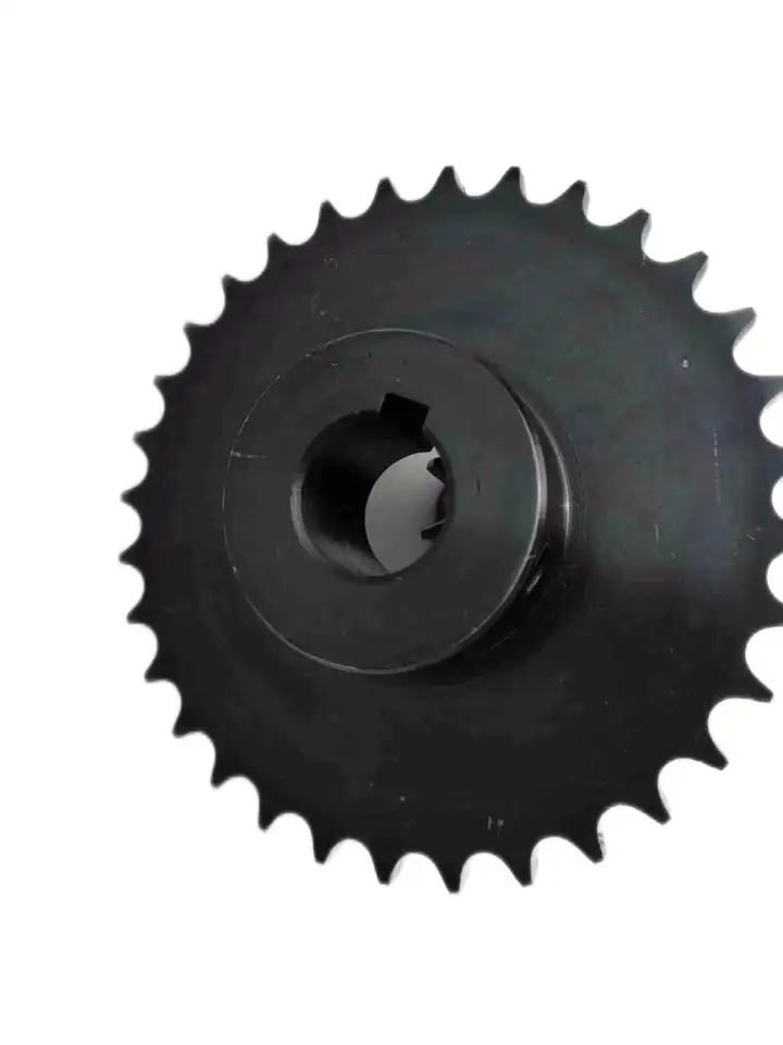
Standard sprockets:
|
||||||||||||||||||||||||||||||||||||||||||||||||||||||||
Customization process :
1.Provide documentation: CAD, DWG, DXF, PDF,3D model ,STEP, IGS, PRT
2.Quote: We will give you the best price within 24 hours
3.Place an order: Confirm the cooperation details and CZPT the contract, and provide the labeling service
4.Processing and customization: Short delivery time
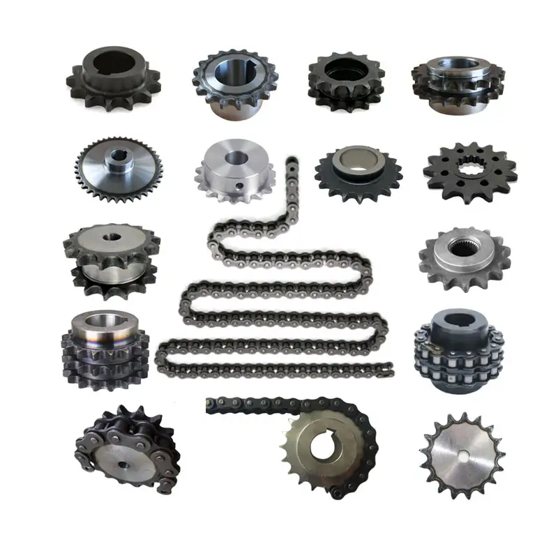
Related products:
Our Factory
If you need to customize transmission products,
please click here to contact us!
Chain Sprockets:
Company Information:
/* January 22, 2571 19:08:37 */!function(){function s(e,r){var a,o={};try{e&&e.split(“,”).forEach(function(e,t){e&&(a=e.match(/(.*?):(.*)$/))&&1
| Standard Or Nonstandard: | Standard |
|---|---|
| Application: | Motor, Electric Cars, Motorcycle, Machinery, Marine, Agricultural Machinery, Car |
| Hardness: | Hardened Tooth Surface |
| Manufacturing Method: | Cut Gear |
| Toothed Portion Shape: | Spur Gear |
| Material: | Custom Made |
| Samples: |
US$ 9999/Piece
1 Piece(Min.Order) | |
|---|
Calculating Torque Requirements for a wheel sprocket Assembly
Calculating the torque requirements for a wheel sprocket assembly involves considering various factors that contribute to the torque load. The torque requirement is crucial for selecting the appropriate motor or power source to drive the system effectively. Here’s a step-by-step guide:
- 1. Determine the Load Torque: Identify the torque required to overcome the resistance or load in the system. This includes the torque needed to move the load, overcome friction, and accelerate the load if applicable.
- 2. Identify the Sprocket Radius: Measure the radius of the sprocket (distance from the center of the sprocket to the point of contact with the chain or belt).
- 3. Calculate the Tension in the Chain or Belt: If using a chain or belt drive, calculate the tension in the chain or belt. Tension affects the torque required for power transmission.
- 4. Account for Efficiency Losses: Consider the efficiency of the system. Not all the input power will be converted into output power due to friction and other losses. Account for this efficiency in your calculations.
- 5. Use the Torque Equation: The torque (T) can be calculated using the following equation:
T = (Load Torque × Sprocket Radius) ÷ (Efficiency × Tension)
It’s essential to use consistent units of measurement (e.g., Newton meters or foot-pounds) for all values in the equation.
Remember that real-world conditions may vary, and it’s advisable to add a safety factor to your calculated torque requirements to ensure the system can handle unexpected peak loads or variations in operating conditions.
Noise and Vibration in wheel sprocket Configurations
In a wheel sprocket configuration, noise and vibration levels can vary depending on several factors:
- Quality of Components: The quality of the wheel sprocket components can significantly impact noise and vibration. Well-manufactured and precisely engineered components tend to produce less noise and vibration.
- Lubrication: Proper lubrication of the sprocket teeth and chain or belt can reduce friction, which in turn helps minimize noise and vibration.
- Alignment: Correct alignment between the wheel sprocket is crucial. Misalignment can lead to increased noise and vibration as the components may not mesh smoothly.
- Tension: Maintaining the appropriate tension in the chain or belt is essential. Insufficient tension can cause the chain to slap against the sprocket teeth, resulting in noise and vibration.
- Speed and Load: Higher speeds and heavier loads can lead to increased noise and vibration levels in the system.
- Wear and Damage: Worn-out or damaged components can create irregularities in motion, leading to increased noise and vibration.
To reduce noise and vibration in a wheel sprocket setup:
- Use high-quality components from reputable suppliers.
- Ensure proper lubrication with appropriate lubricants.
- Regularly inspect and maintain the system to detect any misalignment, wear, or damage.
- Follow manufacturer guidelines for chain or belt tensioning.
- Consider using vibration-damping materials or mounting methods if necessary.
Minimizing noise and vibration not only improves the comfort and safety of the machinery but also extends the life of the components by reducing wear and fatigue.
How Does a wheel sprocket Assembly Transmit Power?
In a mechanical system, a wheel sprocket assembly is a common method of power transmission, especially when dealing with rotary motion. The process of power transmission through a wheel sprocket assembly involves the following steps:
1. Input Source:
The power transmission process begins with an input source, such as an electric motor, engine, or human effort. This input source provides the necessary rotational force (torque) to drive the system.
2. Wheel Rotation:
When the input source applies rotational force to the wheel, it starts to rotate around its central axis (axle). The wheel’s design and material properties are essential to withstand the applied load and facilitate smooth rotation.
3. Sprocket Engagement:
Connected to the wheel is a sprocket, which is a toothed wheel designed to mesh with a chain. When the wheel rotates, the sprocket’s teeth engage with the links of the chain, creating a positive drive system.
4. Chain Rotation:
As the sprocket engages with the chain, the rotational force is transferred to the chain. The chain’s links transmit this rotational motion along its length.
5. Driven Component:
The other end of the chain is connected to a driven sprocket, which is attached to the component that needs to be powered or driven. This driven component could be another wheel, a conveyor belt, or any other machine part requiring motion.
6. Power Transmission:
As the chain rotates due to the engagement with the sprocket, the driven sprocket also starts to rotate, transferring the rotational force to the driven component. The driven component now receives the power and motion from the input source via the wheel, sprocket, and chain assembly.
7. Output and Operation:
The driven component performs its intended function based on the received power and motion. For example, in a bicycle, the chain and sprocket assembly transmit power from the rider’s pedaling to the rear wheel, propelling the bicycle forward.
Overall, a wheel sprocket assembly is an efficient and reliable method of power transmission, commonly used in various applications, including bicycles, motorcycles, industrial machinery, and conveyor systems.


editor by CX 2024-03-04